Sunday, May 20, 2012

Cleaning parts is a blast in my blasting cabinet

This week I got back into the shop mostly on the weekend to clean up more parts so I will have more parts to paint.   If I'm going to mix up some paint and get the sprayer dirty, I might as well have lots of stuff to paint.  I scoured the parts boxes finding all kinds of parts that needed cleaning up so I can repaint them.


Before cleaning began I installed a new air filter and water trap.  In discussion with a knowledgable tool salesman, I found out I needed at least 25 feet of hose or air line between the compressor and the air filter.  Then hook up another air line after the compressor so that the compressed air can get back to ambient temperature and avoid condensing in a single air line.  Now I can operate the blasting box moisture free until the media is exhausted (about 15 minutes) when I have to shut it down, filter the media through a screen, and then put it back into the pressurized vessel for another round of cleaning.  Here's a photo of my new air filter and setup.


Here’s some parts I cleaned:
Windshield middle bracket (2 pieces) on the right


Air vents located at top forward at wingroot. One is clean and the other is as-received condition:


Small assorted brackets, fuel valve selector extension from the valve to the panel, wing root air inlet vents, and various window trim pieces that I found.


I also started to clean the large U-shaped bottom windshield channel piece.

The large curved windshield piece that attaches to the boot cowl is very exciting to be getting cleaned and the most challenging.  Challenging because I cannot fit it into the box and have some of it hanging out.  I still need to scrape some of the window gasket material out of the channel before continuing.  Most pieces I pre-clean them by scrape off the caulking material, and then sand them with aluminum oxide sanding sponges, and then it gets the best results (faster stripping) in the blasting box.


Sunday, May 13, 2012

Wood is Good & Former Owners Re-connect

I've been able to sneak an hour in here and there during the past couple weeks with some progress.  I was inspired to work on it even for little periods of time from an article in a recent Sportair EAA magazine or Kitplanes magazine I read.

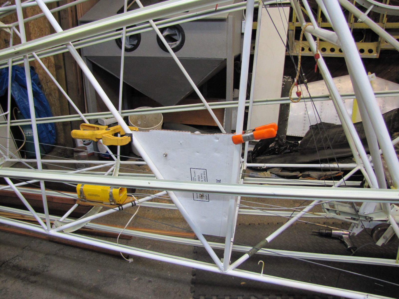
I was able to use the cardboard template for the strobe power supply to make the mounting board which will attach to the frame to hold the power supply.  I used a 1/4" thick piece of marine grade plywood and coated it with satin polyurethane spray about 5-6 coats.  I had to get more hardware from Aircraft Spruce (the clamps and a clamp compression tool) to complete the install.  It's rock solid and won't move.  Here's my completed power supply installation:


I also installed some of the wood pieces that the headliner is attached to in the cabin area.  I used the same pieces that came out of it since they looked really good, so I sanded them and coated them with some brush-on gloss polyurethane I had from a left-over project.  This also gave me time to think about installing the headliner and how the aluminum bows are positioned to give the headliner a nice shape when installed.  Our IA said to be sure to install the headliner before putting on the fabric because it is much easier that way.  I'm not sure where the bow attaches to, but I think it might be some of the same hardware I used to attach these curved headliner pieces over the rear windows so I might have to pull these out again and replace with longer bolts and nylon lock-nuts.

I also started making the cabin dome light and speaker grill support piece using the old one that came out of the airplane.  I want to install a speaker in it too although most restorers I hear do not replace the speaker due to the added weight.  We hope to have a quieter cabin with some insulation, a thicker new boot cowl, and thicker windshield so we might be able to hear it in flight or maybe just listen to the radio or music when it's parked on the ground.  I have to order a speaker yet so that is why I haven't cut the second circle for the speaker:

Studying how the speaker grill/dome light wood is installed I found out it uses Stinson clamps which are spring steel type of clip that goes around the round tube frame and has a part sticking out straight that can be screwed into.  I studied dis-assembled Stinson photos on the internet and some of the dis-assembly photos that were taken when my aircraft was dis-assembled.  I found all the clips in a box of the parts but most had some old paint, rust, and junk on them.  I wanted to clean them up so I got my handmade blasting cabinet set up for the first time since I built it last summer.  I used 80 grit glass bead as a mild blasting medium I thought would work well on aluminum too.  In order to test that, I started dis-assembling the old oleo shock strut cover which is underneath the front seats and had them blasted too.  I removed the old carpeting from the strut cover and started to clean it up to re-use.  I only cleaned up a corner of the oleo strut cover by hand scraping and trying some circular scotchbrite pads on my electric drill (I wanted to use my air drill, but it was late in the evening and I didn't want to wake neighbors).  Anyway, I got a chance to try how difficult it will be to clean this piece up for painting:

Oleo strut cover the way it came--faded blue carpet and all.

Partially stripped cover.  Foreground you can see where I've cleaned it so far.

Stinson clips (cleaned) and various sizes according to frame tube sizes and cleaned oleo strut covers and an aluminum support piece for somewhere I haven't figured out yet.

My homemade blasting cabinet made with warped old plywood, 2x4s, some old glass, a light inside, and some purchased gauntlet rings and gloves to protect my hands.  I wear a filtered mask too just to be on the safe side.  Had trouble with media clogging with water in my lines despite a water trap that I think doesn't work.  I'm going to buy a second water trap to put on the red pressurized vessel to see if it'll trap more moisture there too.


Former Owners Re-connect
I got a surprise email one day from a blog reader who read my blog and also tracked down the tail number.  She is Patty McNabb (formerly Hauch) who's father Don Hauch once owned our Stinson. She and her surviving brother Michael Hauch had a lot of fond memories flying N97917 with their father out of Susana airport in Simi Valley, CA in the early 70's.  Michael even sent a photo of Patty and her father with N97917.

Some of the old paint is still visible on our cowling and now I know where these Cessna wheel pants came from that came with the aircraft.  You can see they were once installed on the aircraft in the photo above and below is the same left wheel pant photo taken today outside my hangar (shop).

I checked the log books to see how recent (since 1960s -1980s) ownership progressed and this is what I found in the documentation on N97917:

Brad Onion and Bill Gray, Simi California purchased May 7, 1964 and sold it December 1, 1970 to Don Hauch, Westlake Village (Patty and Michael's father).  Don Hauch sold it on October 13, 1977 to Eric L. Miller, San Jose, CA.  Eric Miller sold it Dec 2, 1978 to John Stevenson, Moklumne Hill, CA who then sold it to my cousin Mike Ganschow and his wife Amy Newsom in 1979.  My brother and I along with my father's help purchased N97917 in late 2010.  It's cool that people connect with an aircraft and the experiences they have with them and wonder what happened to that wonderful old airplane.  I am delighted and honored to be able to have a hand in getting this bird back in the air--the sooner, the better.

Thursday, April 26, 2012

Trim cable install and cardboard mockups

Wow, it's been a long time since I posted something.  I was shocked to see the last time I worked on the aircraft since my last work log entry.  Let's just say, life had some higher priorities which I took care of (mostly) and was able to sneak in an hour or 2 this week.

I got the elevator trim cable back from Univair who shortened it for me and now it fits perfectly.  I installed the phenolic blocks that the trim cables pass through.  You can see the cabin roof crank assembly in the background.  This is what I will turn to adjust the elevator and rudder trim tabs to fine adjust the flying characteristics of the Stinson.  One cable controls the elevator (going through the phenolic blocks) and the cable laying on top is for the rudder bungee trim system.  It's pretty cool to turn it and see the tail elevator adjustment screw go in and out.

Here's the rear elevator trim pulley assembly.  I had to work at it to get the set screws to line up in the holes on the shaft.  There are some final nut and bolt adjustments so don't freak out that the bolts are not tightened in the photos--they will be!


In testing the final assembly of the trim tab end which spins on the threaded rod at the end of the cable in the flexible housing, it wouldn't fit so I had to get a thread die and just screw it on.  There were a few threads at the end that were bent down, but I could fix it with the die that I could easily screw on by hand.  Now the threaded rod screws perfectly onto it.  I will grease it up before I put it together.

Another project is making a bracket to hold up the ELT antenna that I am putting in sideways in the top former.  I saw a similar installation on John Baker's website and since I got my ELT from John I thought I would do a similar install to make it nice and neat inside the fuselage so it isn't another antenna.  I made a cardboard mock up first and then taped it in to see how it fit.  Don't worry about the square hole, I will make a round hole and have a plastic insert that will snap in to insulate the antenna from the frame.  Here's the photos of the cardboard.  Next posting, I will transfer the pattern to some scrap sheet aluminum and then fit the final assembly onto the fuselage former hat section (that's what they call it).  I held it in place temporarily with blue painters tape.


Last month, Kevin and I took a Sportair workshop over a weekend at the Watsonville, CA airport.  I took aircraft aviation electronics and Kevin took a sheet metal fabrication class.  I learned a lot about how to install wires and electronics.  I knew this was coming up to wire the instrument panel, the antennas, and the strobe and marker lights.  I'm going to start with the strobe and marker lights.  With the purchase of this plane it included a new-in-the-box Whelen strobe and marker kit.  It has a centralized power supply and I've seen them installed in the fuselage usually under the baggage compartment.  Since we don't have a baggage compartment, I've seen other installations with the power supply mounted on a piece of plywood on the steel tube frame sidewall.  I made up a piece of cardboard first and temporarily screwed the power supply to it and then clamped it to the frame.  I mounted it a little sideways so that if maintenance required, I could easily check the connections once the cabin backwall is removed.  Here's a photo of it.  Looks good and next time, I will transfer it to plywood, spray with poly urethane and use adel clamps to attach to the frame.


That's it for this entry.  Next one will be much sooner.  Soon I will install the panel and the wiring will begin!

Sunday, January 1, 2012

Rivets, Phenolic, Stringers, Fuel System

Happy New Year!  A lot has happened since the last post.  A lot of work done during the Christmas holiday. I worked on replacing the phenolic pieces for the elevator control cable and the elevator trim cable.  Here's the old pieces and the new ones I built from linen phenolic purchased from Aircraft Spruce:


Here's the phenolic installed in the base of the vertical stab.


I tried installing the new elevator trim cable that came with the plane, but found it's 29' 6" length was too long.  The rudder trim cable has no turnbuckle and I have it adjusted to approximate tension.

Here's a photo of the two ends of the cable overlapping

I talked to Univair who said I could send in my cable so it can be shortened and a new bolt end put on it with a special swageing tool I don't have.  Kevin helped me measure a new elevator trim cable and we're going to have it cut to 29' 2".

I installed the belly formers and looking at it from the bottom front of the airplane you can really see the shape of the fuselage.

A couple days after Christmas, Kevin, Dad and I drove up to Corning, CA and visited Earl Allen for some parts we need for our ship.  It turned into an all-day field trip and we had a great time.  Earl was very gracious with his time and knowledge.  Took lots of photos of various Stinsons Earl has.  Earl has added a new building which is now full of fuselages and wings with more to come.  We purchased a 1/2" fuel system including fuel selector valve, gascolator, and L and R fuel tank lines, landing gear to fuselage fairings, an original Stinson starter switch, and a cabin ceiling light and speaker grill.  I could tell the field trip to Corning really pumped up Kevin and I couldn't wait to get back into the hangar to keep working.

A few days later, Kevin and I spent a day working on the airplane riveting the top former onto the fuselage.  I practiced riveting on some scrap the week before, but it was easier riveting with 2 people with one inside the cabin and the other bucking the rivets on the outside.  I had already riveted some of the right side of the top former and the bottom fuselage former near the landing gear.  I had to re-do some rivets because my rivet gun moved off the rivet head.  We also used some Cherry Max blind rivets for some areas we couldn't get the bucking bar into.


I cleaned up and installed the new fuel lines and valve but discovered I routed the lines incorrectly (inside) the fuselage frame members.  We found this out when we tried installing the instrument panel and it wouldn't fit.  Also discovered our original Stinson 108 panel would not fit in the frame because of some welded brackets that were confusing at first. Then, when I put the panel on that came with the plane these new brackets made sense. I also looked in my various photos and online photos to see if they had these brackets and all Stinson 108 fuselages don't have them.  Here's us trying to fit an original Stinson instrument panel in and the top "L" shaped bracket is blocking us from the install.


Old panel sitting on the unusual brackets that will have to be removed to install the original panel.

New 1/2" fuel lines after I cleaned them up and re-installed them correctly OUTSIDE the fuselage frame members.

We also installed the bushings for the control wheel shafts.  Kevin had these re-chromed and we made sure they had free travel on the bushings before we drilled and installed the 2 screws for each bushing.  It was very satisfying seeing the control shafts move freely in place.  We still need to re-drill some mounting holes on the new universal joints on the control yokes.


We also decided to re-build the boot cowls with thicker .032 aluminum instead of the .024 aluminum that it has.  It will make the cabin quieter and we saw some good examples of this work that Earl had.  We already had the .032 aluminum too so the decision was easy.  I was told the fuel selector knob shaft was the same for the 3/8" fuel and 1/2" fuel valve, but when I went to fit my old shaft on it, the cotter pin holes didn't match up (not even close).  So I'm going to buy one from Earl.

Next up will be some woodworking for the cabin trim, a new mounting platform for the Whelen strobe power supply, installing the ELT antenna in the top fuselage stringer/former, cutting those old panel welded brackets off and fitting an original Stinson instrument panel into our bird.

Saturday, December 10, 2011

Hardware and Puzzles

More progress on the plane this week.  I am grateful I can walk from my house to the shop where the airplane is and jump back into projects.  This week was full of figuring out what goes where from the various piles of parts and boxes around the shop.  The good news is, there are less parts laying around and the airplane is a step closer to completed.  Only the major structural parts of the Stinson have the hardware specified in the parts manual--it's up to the builder to know what to use where for everything else.  I got new elevator cables from Univair this week and installed them.  There are a pair of fairleads that the elevator cables pass through on their way aft to the elevator horn


However, I wasn't sure if the up elevator cable went in the upper fairlead or visa versa.  I pulled them back taught trying to figure out the correct routing and visualizing how they should work pulling on the cables near the tail while the control column up front went back and forth.  I don't know why it was so hard for me to figure this out, but after 15 minutes of sawing back and forth I think I satisfied myself that the elevator cables are rigged properly.

I also put in the ELT unit.  Hope I never have to use this piece of equipment--it I did...well, you'd know where to find me.

I moved onto the door frames and rear cabin window frames.  When I first fitted the door frames back onto the steel fuselage, there was a 1/4" gap running down the backside of the cabin door and the aluminum door frame.  I thought this can't be right to squeeze these together with a screw so I went to the parts piles and found wooden shims that had holes in them that lined up perfectly with the holes in the door frames and they were labelled (thanks Mike) "L" and "R".

Once the door frames were screwed in, I also put in the assist handles on the front of the frame for when we will need to do installation in the cabin.  I was able to find some used truss head screws in the assorted bottles and coffee cans that fit the door frame holes and then matched them with new truss head screws that I had acquired with the plane.  In addition, I attached the rear cabin window frames which I was happy to do since there was this particular bracket that always hit my head when I stuck it inside the side of the cabin before.  Now the bracket is attached to the window frame.


I installed the side stringers and just temporarily dropped in the cotter pins that hold them in.  These stringers will have the fabric for the skin of the airplane fitted over them.


There were more parts for the front belly and sides underneath the cabin doors that I got out and cleaned off the dust.  This is where I had to stop because I wasn't sure how these were attached so I posted a question on a Stinson web group and also asked another Stinson builder and found that most of these are attached with rivets and some safety wire.  I'm working on purchasing or borrowing a rivet gun (I already have a large assortment of aviation rivets that came with the project).  The next posting will surely be riveting!  Lastly, here's a photo of the proper attire which I aspire to use this airplane for when it's completed.  It just arrived in the mail.