I got the elevator trim cable back from Univair who shortened it for me and now it fits perfectly. I installed the phenolic blocks that the trim cables pass through. You can see the cabin roof crank assembly in the background. This is what I will turn to adjust the elevator and rudder trim tabs to fine adjust the flying characteristics of the Stinson. One cable controls the elevator (going through the phenolic blocks) and the cable laying on top is for the rudder bungee trim system. It's pretty cool to turn it and see the tail elevator adjustment screw go in and out.

Here's the rear elevator trim pulley assembly. I had to work at it to get the set screws to line up in the holes on the shaft. There are some final nut and bolt adjustments so don't freak out that the bolts are not tightened in the photos--they will be!


In testing the final assembly of the trim tab end which spins on the threaded rod at the end of the cable in the flexible housing, it wouldn't fit so I had to get a thread die and just screw it on. There were a few threads at the end that were bent down, but I could fix it with the die that I could easily screw on by hand. Now the threaded rod screws perfectly onto it. I will grease it up before I put it together.
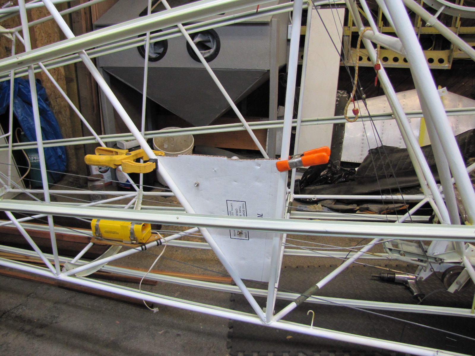
Another project is making a bracket to hold up the ELT antenna that I am putting in sideways in the top former. I saw a similar installation on John Baker's website and since I got my ELT from John I thought I would do a similar install to make it nice and neat inside the fuselage so it isn't another antenna. I made a cardboard mock up first and then taped it in to see how it fit. Don't worry about the square hole, I will make a round hole and have a plastic insert that will snap in to insulate the antenna from the frame. Here's the photos of the cardboard. Next posting, I will transfer the pattern to some scrap sheet aluminum and then fit the final assembly onto the fuselage former hat section (that's what they call it). I held it in place temporarily with blue painters tape.


Last month, Kevin and I took a Sportair workshop over a weekend at the Watsonville, CA airport. I took aircraft aviation electronics and Kevin took a sheet metal fabrication class. I learned a lot about how to install wires and electronics. I knew this was coming up to wire the instrument panel, the antennas, and the strobe and marker lights. I'm going to start with the strobe and marker lights. With the purchase of this plane it included a new-in-the-box Whelen strobe and marker kit. It has a centralized power supply and I've seen them installed in the fuselage usually under the baggage compartment. Since we don't have a baggage compartment, I've seen other installations with the power supply mounted on a piece of plywood on the steel tube frame sidewall. I made up a piece of cardboard first and temporarily screwed the power supply to it and then clamped it to the frame. I mounted it a little sideways so that if maintenance required, I could easily check the connections once the cabin backwall is removed. Here's a photo of it. Looks good and next time, I will transfer it to plywood, spray with poly urethane and use adel clamps to attach to the frame.

That's it for this entry. Next one will be much sooner. Soon I will install the panel and the wiring will begin!